Laser Scanning & Adaptive Welding
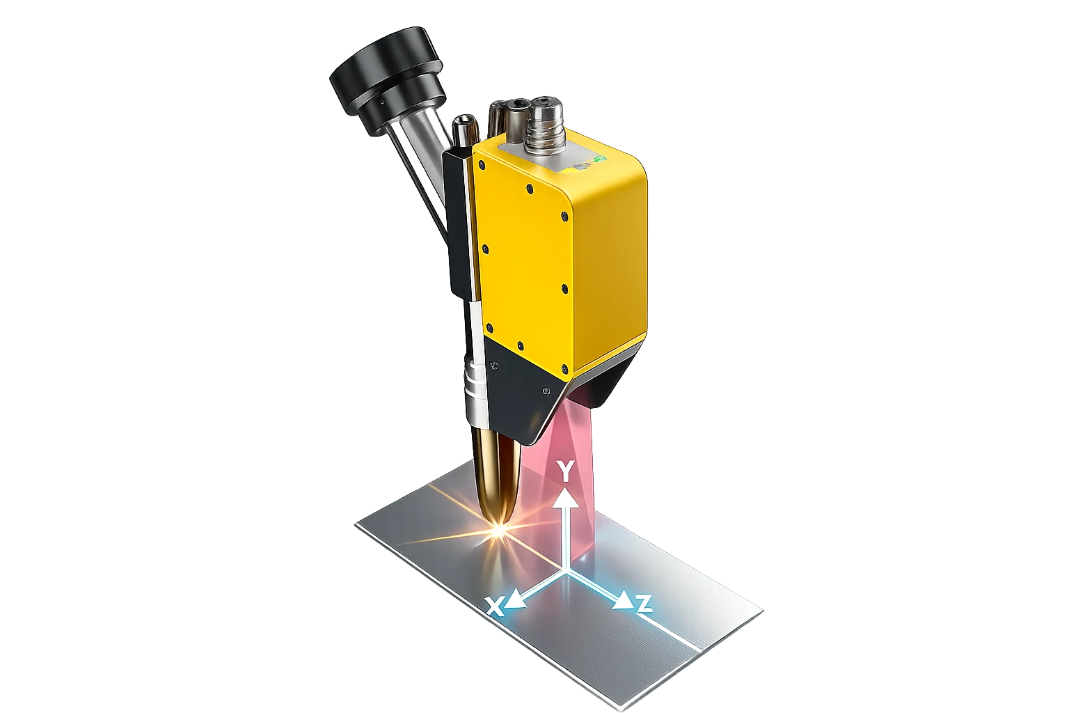
Pre-weld laser scanning measures the part as built and the scan path is simulated on screen in real time. From that measurement the software automatically recomputes pass count, pass sequence and welding parameters; no manual programming. Even when heat distorts the part mid-weld, laser tracking keeps the torch aligned to the shifting joint; with no reprogramming, the robot welds the real part in front of it rather than the theoretical model.
 Pass Planning from As-Built Geometry
The technology's role in the cell
In heavy fabrication a part never arrives at nominal size. Cutting tolerance, distortion after tacking, assembly gaps and plate flatness mean the real groove geometry always differs from the drawing.
A robot running a fixed program cannot see that difference; the result is under- and overfilled beads, undercut and rework. The laser scanner ahead of the torch scans the joint immediately before welding: groove angle, root gap, depth and fill volume are measured.
From that measurement the software recomputes how many passes are needed, where each pass sits and which parameters apply. On thick sections with variable gaps every part receives its own pass plan; the robot adapts instead of stopping.
In shipbuilding, wind towers, pressure vessels and thick structural steel, robotic welding does not deliver the expected return without this capability. Robentex engineers adaptive welding into these applications as part of the system, not as an option.

Capabilities
- Weld groove geometry measurement
- Root gap and misalignment detection
- Path offsetting against the real part
- Section-based automatic pass calculation
- Variable-groove fill strategies
- Inter-pass temperature supervision
See this technology on your own part.
We start with a sample welding trial and evaluate the results together.